Tech Tips & Information
Mapping The Valve Timing of a
Honda Gx160
|
Tech Tips & Information |
Mapping The Valve Timing of a Honda Gx160
 |
|
 |
This article has been written to assist the DIY mechanic learn more about the Honda Gx160 engine. This year, 2007, the Cadet class of Honda has discarded engine sealing and made the position of the cam gear 'free' (if your rules also allow the camgear to be 'free' then it may be of use to Snrs as well). The repositioning of the cam gear on the crankshaft makes the engine more efficient as a race engine . Mass production of the engine means some engines are better than others but every engine I have examined can benefit from repositioning of the cam gear in relation to the cam.
NOTE: Any modification(s) is/are performed at your own risk. This text is for information only and should not be attempted without the correct tools and engineering training. If in any doubt, please consult a professional.
How much should I move the gear... and in which direction? Should I set the engine for torque or speed? - All relevant questions. Let us examine the procedure and all will become clearer very soon. Let us have a look at the tools needed to establish the actual position of the cam gear/timing of valves.
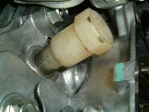
We need to use a timing disk, a piston stop and a DTI (Dial Test Indicator) with suitable bracket.
 |
|
 |
|
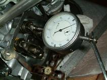 |
| Timing Disk | Piston Stop | Dial Test Indicator (DTI) |
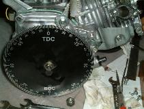
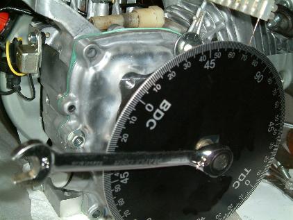
As seen in the photos the timing disk mounts on the end of the crankshaft and is held in place with washers and the normal 5/16ths UNF clutch bolt. It is positioned in such a way that we can see it rotate as the valves open and shut. The disk needs a pointer as a reference and I suggest you mount a piece of stiff wire so that the pointer accurately indicates where we are during the rotation of the crankshaft and stays accurate during the mapping of the valves/cams.
The old adage of 'measure twice, cut once ' is relevant here and repeatability of any measurement is crucial to the accuracy of the whole procedure. Be prepared to repeat your work over and over until you are completely satisfied that you have an accurate set of readings.
The piston stop is pretty much self explanatory and all I would add is that to use it you really need to screw it all the way in the plug hole as stripping threads on either gauge or plug hole is a pain to correct.
The DTI is mounted, using a suitable bracket, in such a way that we can measure the opening and shutting of the individual valves, via the rocker arms. The stroke of the DTI is probably hard pressed to measure the full stroke of the valve so be prepared to reposition the DTI for the top and bottom of the valve stroke. In this test we are only measuring the point the valve starts to open, the fully open point of the valve and the fully closed point of the valve. These readings will show as the DTI's pointer stopping and rotating in the other direction. ( all will become clear as you work through the procedure).
Finding TDC!
Mount timing disk with TDC mark somewhere near top. Mount pointer on engine so
it points to face of timing disk. Screw piston stop into spark plug hole. Rotate
engine crankshaft clockwise until it comes solidly up against the piston stop.
Take reading from timing disk/pointer Rotate crankshaft anticlockwise until it
comes solidly up against the piston stop. Take reading from timing disk/pointer.
 |
|
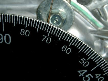 |
Compare the two readings and split the difference between them. ie if clockwise rotation of crank stops at 74 degrees and anticlockwise rotation of crank stops at 70 deg then you would move the timing disk manually so the pointer indicates 72 degrees. Re check the readings and if it stops at the same numbers each rotation then you have accurately found TDC on your timing disk! Remove the piston stop and rotate the crankshaft until the pointer indicates TDC on the disk. Continue rotating the crankshaft, anticlockwise and you can watch the valve rocker arms open and shut the valves during the four stroke cycle.
The Four Stroke Cycle
The four strokes are:
This simplistic overview does not describe the position of the inlet and exhaust valves throughout the four stroke cycle.
The Induction stroke consists of the inlet valve opening, staying open for a set period and then closing. The total number of degrees that the valve works for is called the 'duration'. (to check for the optimum valve 'lift' we would mount the cylinder head on a flow bench and test for amount of air flowing at various valve lift positions. The most airflow is the best valve lift. To get this lift we may have to alter the rocker arm to make the valve open more, but we are now in the realm of tuning and not all rules allow the mod so check before altering rockers).
 |
 |
|
|
|
||
|
|
||
The point at which the inlet valve opens is a compromise due to the other strokes. The inlet valve procedure is a big plus for the engine performance as without it we are going nowhere! Can we have it open early, stay open lots and almost never close? - No, sorry... the other strokes need time to work and deserve consideration. The length of time the inlet valve stays open, the duration, decides how much air fuel mixture is allowed into the cylinder and we know the bigger the bang the faster we will go so lets try and maximise the time the inlet valve is open.
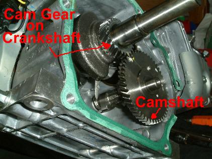
Advancing the timing of the inlet cam would normally require the cam to be welded and machined to the new improved profile that opened earlier in the cycle. In our case we can simply move the cam gear on the crankshaft to achieve the same effect.
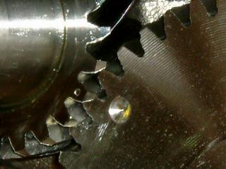
The amount we move the camgear is a variable from engine to engine and can only be trial and error for most engines due to the mass produced tolerances of how accurately the gear is positioned /pressed onto the crankshaft. Most Gx160s seem to have the timing mark of the camgear positioned approx 60deg from the centreline of the crank web and the keyway. If we try to have the inlet valve opening 4 degrees earlier than normal we should see the performance increase on the dyno and on the faster tracks.
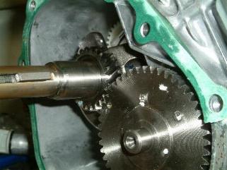
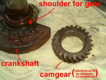
Fine tuning of the best position for the camgear is close to this point and a move or two will give you that edge over the standard camgear position. How do we move the camgear on the crankshaft? We can either remove it completely with a puller and press it back on in the new position...
 |
|
 |
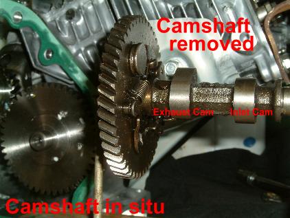
...or rotate the gear without removing the actual gear. The gear is an interference fit on the shaft and does not move easily! Before and after the camgear 'move' we should map the inlet valve to see the degree position that the valve starts to open. (taking my word as gospel is one thing but is much better if the theory is backed up with your own data for future information).
At present we have only considered the inlet valve as the variable. If we wanted we could map the exhaust valve and learn more about how the two valves work together and how both are compromises unless we separate them in a new design. The last thing I will mention on cams is the possibility of creating greater 'lift' by building up the lobe of the cam so it moves the valve train more. It is best left to the keen tuner in 'open class' racing.
Using a DTI to Map Valves/Cams (to check when the inlet valve actually opens)
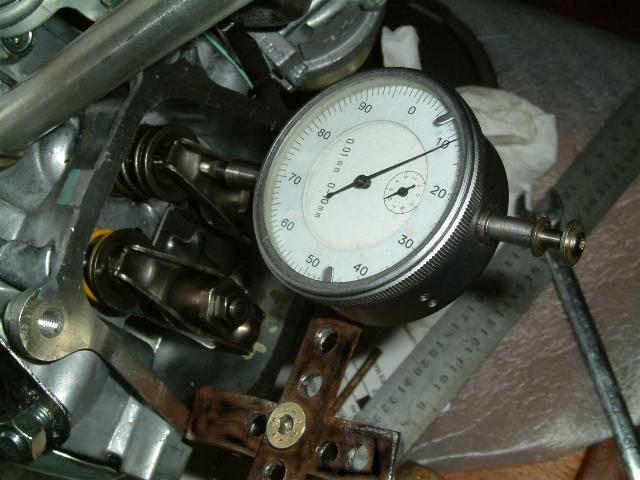
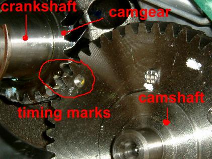
So... rotate the crankshaft until the DTI pointer moves, zero the dial at this point so you can easily read/check the reading and repeat until it is exactly zero at every try. (Tip : if you go past the point you wanted then reverse the crank rotation well past the point of retry so all slogger is taken up). With the DTI pointer at zero you can now look at the timing disk and read off the actual position of the inlet valve opening (you did zero the timing disk at TDC didn't you?)
We could carry on and map the whole of the inlet valve cycle, as it opens, stays open and then closes, stays closed. This map would help us understand the engne better but for now we are only really looking to see when the inlet valve starts to open and how much we have moved the opening position after moving the camgear on the crankshaft.
Additional Information:
This article was produced by Brian Pollard, author of "Preparing the Gx160 for 'open' racing" which is available on CDROM, in multimedia format, as an e-book, and in paper form. All enquires should be sent to the above e-mail address.
| News | Karts & Karting |
Notice Board |
Market Place |
Companies Directory |
Tracks Directory |
Events Calendar |
Race Results |
Photo Gallery |
Links |
Copyright © 1996-2018 UK Karting Comments, Suggestions etc. mail@karting.co.uk |