
Tech Tips & Information
The Preparation and Jetting
of the Rotax Carburettor
|
Tech Tips & Information |
The Preparation and Jetting of the Rotax Carburettor
The Rotax Power Valve (PV)
 All PV systems vary the duration of the exhaust port open time, which gives
the engine usable low end power combined with excellent top end power.
All PV systems vary the duration of the exhaust port open time, which gives
the engine usable low end power combined with excellent top end power.
This is of course the reason why most gearbox karts blank off their PV's, as with the use of a gearbox the engine will always be in the rev range of the open PV position.
The PV in the Rotax Max effectively operates in 2 positions - closed and open.
When the PV is closed, the engine produces good low speed torque/power curves
that drop off rapidly just above 7500rpm. When the PV is open, the engine
produces good high speed torque/power curves that drop off rapidly just below
7500rpm. So in simple terms if you want to use your engine at 7500rpm and below
then the PV must be closed and conversely if you want good torque and power
above 7500rpm then the PV must be open. However it must be remembered that
adjusting the PV spring pressure by turning the red knob (2) spring pressure
adjuster on top of the PV cover does not alter the torque/power curves, it
simply alters the engine speed at which the PV changes position, thus switching
between the curves.
If the adjuster (2) is set too far out, the spring compression force will be low
and the valve will open at too low an engine speed, giving a torque/power dip
below 7500rpm. Similarly, if the adjuster (2) is set too far in, the spring
compression force will be too great giving a torque/power dip above 7500rpm.
See page 98 of the Rotax Max Operators manual.
When the PV is adjusted correctly the change over between the two torque/power
curves should be seamless as this setting will give the overall best
performance. If you have adjusted your PV to a position were you are able to
notice a dramatic change in the torque/power curve then this adjustment is wrong
and you will need to re-adjust your PV spring pressure, to a position where the
change is hardly noticeable to the driver.
The most common symptoms which may cause poor performance from the PV are:
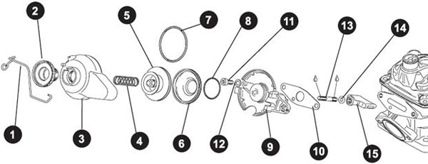
If your engine has been popping, check that the bellows (6) has not blown off the piston (5). The sudden rise in exhaust pressure caused by the popping (exploding of unburned fuel in the pipe) may be sufficient to blow the bellows (6) off. Which will cause the power valve not to open fully and will result in loss of top end performance, however the new green bellows (6) are not prone to this problem.
Never be temped to stretch the PV springs (4), always screw the adjuster in or out to change the revs at which the PV opens and closes. If you stretch the spring (4) it changes the spring characteristics, then you are only guessing. The PV spring adjustment can cause big losses of power if not set correctly.
Clean the PV blade (15) after every race to ensure that it always moves
freely in its slot, always checking for correct alignment of the PV sealing
gasket (10).
Don't forget that the ignition timing curve takes a sharp dive to 20° after TDC,
at around 12,500 RPM and acceleration from then on only get slower. If you are
coming out of a corner above 12.500 RPM and you are not already accelerating you
will not get any faster. In this situation reduce the axle sprocket by 1 or 2
teeth. As the more acceleration you have when you reach 12,500 RPM the more
likely you are to reach higher speed ultimately.
An import final note regarding driving the Rotax Max with a PV fitted: As
explained above, the exhaust valve position is controlled by the amount of
backpressure in the exhaust pipe, to ensure design performance your must always
check that you have a good seal at the exhaust header ball joint with the pipe,
especially after having changed the rear sprocket/chain tension or otherwise
moved the engine on its mount.
Remember also that it is possible at some tracks, depending on the layout and
driver style, when you are off the throttle braking for a corner, to reduce
pressure in the exhaust chamber causing the exhaust valve to close, lowering the
effective exhaust port height while engine RPM is still above 7,500 RPM.
Now (and this is the important bit!) when you come back on the throttle if the
engine revs are greater than 7,500 with the exhaust valve closed, this will
cause a considerable lag in engine response, the classic "BOG", to prevent this
from happening in the first place, always use some throttle while braking which
will maintain exhaust pipe backpressure sufficient to maintain the PV in the
open position. However, not too much as excessive power braking will kill your
clutch! This symptom is the main reason why you may have seen many of the
factory KF1/2 teams now fit a power valve sensor to monitor the PV position
during test and race track sessions.
Carburettor Types
 The
Rotax carburettor is available in two different models, the VHSB 34 QD or QS;
the only difference between these being; the QS has the idle speed and airscrew
adjusters on the opposite side of the carburettor. However, of greater
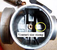
significance is the fact that each carburettor can have either a 12.5 or 8.5
venturi insert. The venturi is available as a replacement part therefore the QD
or the QS could be converted.
The
Rotax carburettor is available in two different models, the VHSB 34 QD or QS;
the only difference between these being; the QS has the idle speed and airscrew
adjusters on the opposite side of the carburettor. However, of greater
significance is the fact that each carburettor can have either a 12.5 or 8.5
venturi insert. The venturi is available as a replacement part therefore the QD
or the QS could be converted.Carburettor Race Preparation
 The most important aspect of race preparation is cleanliness and I really
mean surgical cleanliness. The carburettor body is made with many tiny internal
passages and some of the various jets have very small holes, all of which need
to be maintained scrupulously clean for the carburettor to perform as it was
designed.
The most important aspect of race preparation is cleanliness and I really
mean surgical cleanliness. The carburettor body is made with many tiny internal
passages and some of the various jets have very small holes, all of which need
to be maintained scrupulously clean for the carburettor to perform as it was
designed.
Following each weekends racing or each days racing if carb problems are
encountered, start by unscrewing the carb top and removing the slide spring,
slide and tapered needle. Then remove the carb from the engine and carefully
drain the fuel from the float bowl into a suitable container.
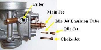
Remove the float bowl, the main jet, choke and idle jets then carefully unscrew
the idle jet emulsion tube from the threaded hole below the idle jet. Remove the
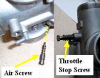
fuel inlet filter and check its condition. Also remove the air screw and the
throttle stop screw.
At this stage I place the carb body and parts in an ultrasonic cleaner and leave
it for a full cleaning cycle at 80C, however if you do not have one then use a
good carb cleaning aerosol, followed by a careful blast clean of all passages
and jets with compressed air.
Take care to use safety goggles, as an eye full of solvent is, as I can testify, very painful indeed.
Re-assembly and adjustment
 You are now ready to re-assemble your carb, first replace the fuel inlet
filter and tighten the 12mm cap ensuring that the fibre washer is in good
condition to prevent any leaks. Carefully replace the air screw turning fully in
(not too tightly or you may damage the tapered seat) and then turning out 2
turns, (you will later adjust this screw with the engine running on fast idle)
simply slowly turn out the screw from this initial position up to a further 1 ½
turns (anti-clockwise) until the fastest idle speed is obtained (setting range 2
to 3 ½ turns anti clockwise from fully in).
You are now ready to re-assemble your carb, first replace the fuel inlet
filter and tighten the 12mm cap ensuring that the fibre washer is in good
condition to prevent any leaks. Carefully replace the air screw turning fully in
(not too tightly or you may damage the tapered seat) and then turning out 2
turns, (you will later adjust this screw with the engine running on fast idle)
simply slowly turn out the screw from this initial position up to a further 1 ½
turns (anti-clockwise) until the fastest idle speed is obtained (setting range 2
to 3 ½ turns anti clockwise from fully in).
Replace the throttle stop screw, again gently turning fully in and then backing
out ½ a turn.
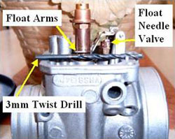 Next place the carb body upright on a level surface as illustrated to the
left. Place a 3mm twist drill onto the carb body and adjust the float arms until
level and parallel with the top of the twist drill. Repeat this process for the
other arm of the float lever. The level of the floats can be adjusted to other
measurements (see below) but 3mm is my recommended starting point and should
always be used for running in a fresh engine. It is worthwhile noting at this
point that a constant level in the float camber is vital to the consistent
performance of the carb in maintaining the correct fuel/air mixture across the
throttle opening range.
Next place the carb body upright on a level surface as illustrated to the
left. Place a 3mm twist drill onto the carb body and adjust the float arms until
level and parallel with the top of the twist drill. Repeat this process for the
other arm of the float lever. The level of the floats can be adjusted to other
measurements (see below) but 3mm is my recommended starting point and should
always be used for running in a fresh engine. It is worthwhile noting at this
point that a constant level in the float camber is vital to the consistent
performance of the carb in maintaining the correct fuel/air mixture across the
throttle opening range.
To ensure this correct operation, the floats must be in good condition (always check that they are not leaking & replace if not sure) and able to move freely on their guides. The float needle valve must cut off the pumped fuel flow when closed, this can be checked by using a carb pop-off pressure gauge on the fuel pipe connection, pump up to 3 psi with the float levers gently held down and watch for any leaks, again if in any doubt replace the float needle valve assembly.
The rules dictate the size of float needle valve so all we can do is to ensure it is always working as designed. Now replace the idle and choke jets, taking care not to over tighten the idle jet emulsion tube, check the float bowl gasket condition and replace if necessary, carefully re-fit the floats and float bowl (don't forget your Italian - "Alto" means top).
Now at this stage in an effort to maintain carb cleanliness and not undo this
careful preparation, I always wrap my re-built carbs in cling film and then a
soft clean rag to protect against knocks, only refitting to the engine on race
day. This practice I find also helps to eliminate any condensation issues with
warm carbs when stored in a cold garage. That said a good carb should always be
kept warm under your pillow!
 Because we are restricted by the rules to use only the 5.2 gram or 3.6 gram
floats and are not able to use the alternatives manufactured by Dellorto, we
have to adjust the float heights by carefully bending the float arms to simulate
the other floats if we believe this may be required to enhance performance.
Because we are restricted by the rules to use only the 5.2 gram or 3.6 gram
floats and are not able to use the alternatives manufactured by Dellorto, we
have to adjust the float heights by carefully bending the float arms to simulate
the other floats if we believe this may be required to enhance performance.
However if you chose to take this route in testing, please ensure you use a catch tank on the fuel bowl vent pipes, so that the proper operation of float needle valve can be checked, as adjustment outside the normal range may sometimes jam open this valve flooding the carb and without a catch tank fitted this may not be readily detected.
Why change the float heights? Well, a lower fuel level will weaken the fuel/air mixture across the entire operating range, conversely a higher fuel level enriches the air/fuel mixture across the entire operating range - you will find this is a very useful tuning tool. The standard setting for most Dellorto carburettors is 6mm but you need to experiment with these settings to find the optimum, as I say above I have found that 3mm is a good starting point for the Rotax Max but you may well find with experimentation, a better setting that will suit your individual carb and engine.
It is also worthwhile at this point to mention the Mikuni fuel pump used in the Rotax classes: This pump is not the strongest pump of the Mikuni range and as such may let you down by not maintaining the correct float chamber fuel level if not properly prepared. I rebuild my pumps prior to each race meeting (carrying a spare in my toolbox wrapped in cling film and a rag as with the carb) this is a simple process to complete and is a worthwhile precaution. Don't forget the simple check is, that if the fuel can run back through the pump towards the fuel tank then its time for a rebuild.
Jetting Theory
Now at the perfect air/fuel ratio (for petrol) of 14.7 to 1 (measured by mass) all of the fuel and oxygen molecules are burned in the combustion process. However whilst this ratio may keep the environmentalists happy we are seeking the maximum power and torque from our engines, this will be found at a ratio of around 12.8 to 1. However, given that we are using 2% oil in our fuel we need to remove 2% from the air side of this equation. This would give an approximate target air/fuel ratio of 12.5 to 1.
Keeping a two-stroke at optimum power requires frequent jetting changes as the atmospheric conditions change. As the temperature, barometric pressure, or relative humidity change; the relative amount of oxygen in a given volume of air changes. Because the engine ingests a fixed volume of air per cycle, the amount of oxygen available per cycle varies with the weather. Therefore, to maintain the optimum air/fuel ratio, we must adjust the jets and needle position in the carburettor.
In the Rotax class we have two needles available the K27 and the K98. These needles have different characteristics determined by their dimensions. The needle in combination with the needle jet, control the air/fuel ratio from ¼ to ¾ throttle opening independent of the main jet selection. This is of course provided that the main jet selected is larger in area than the area between the needle-jet and the selected needle tip.
In the case of the Rotax classes using the FN 266 needle-jet and a K27 or K98 needle this would be a minimum main jet size of less than 100, above which the needle and needle-jet would function as designed by Dellorto. However it must be recognised that the overall equivalent jetting in the needle operating range is somewhat above this main jet equivalent, as the fuel flows from all of the other circuits in the carb body at the same time as the needle operates.
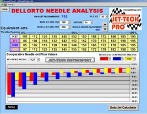 This is illustrated here on the right with a screen shot from my needle
comparison software. You can see clearly the progressive jet equivalents
provided by the needle-jet/needle combination using an FN 266 needle-jet and 165
main jet setting. Whilst I have designed this software with a database
containing the full range of 'K' series needles used by other classes, it does
serve to illustrate the effects of both the K98 and K27 needles at the 165 main
jet selection.
This is illustrated here on the right with a screen shot from my needle
comparison software. You can see clearly the progressive jet equivalents
provided by the needle-jet/needle combination using an FN 266 needle-jet and 165
main jet setting. Whilst I have designed this software with a database
containing the full range of 'K' series needles used by other classes, it does
serve to illustrate the effects of both the K98 and K27 needles at the 165 main
jet selection.
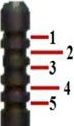 So to summarise in the range ¼ to ¾ throttle opening for the Rotax classes,
your main adjustment is the needle clip position - clip1 being the weakest
setting and clip 5 being the richest setting.
So to summarise in the range ¼ to ¾ throttle opening for the Rotax classes,
your main adjustment is the needle clip position - clip1 being the weakest
setting and clip 5 being the richest setting.
A change in clip position will change the mixture strength in this vital operating range, a quick analysis of your data from any track session will tell you that this range is possibly 70% to 90% of your track time, and an area in which most gains are to be made.
A quick word here on jetting software, any software that gives the needle
position as a simple progression as air temperature rises from say a main jet of
162 at P4 then 162/P3 then
162/P2 then 162/P1 and then changes to 160/P4 is, to put it simply, WRONG and
must not be used by any serious engine tuner to maintain optimum jetting!
So having learned the theory lets try to put it into practice!
Just before we do first you must learn to drive the carb! Every time the
throttle is opened suddenly, the air speed in the choke barrel drops. In
two-stroke engines this does not normally upset good engine running, but in a
Rotax because of the relatively large choke size at 34mm, this drop in air speed
may, for a moment cause the atomiser to deliver insufficient fuel. So do not
snap open the throttle - it is not the on/off switch of say a Formula A engine.
In a Rotax it's more of a quick press of the throttle, than a stamp. However you
will quickly learn this technique and with optimum jetting it can all but be
eliminated.
Jetting Practice
If you have carefully followed my preparation advice above then 90% of the
work is done and you simply have to fine tune your setup. Do not undo this
preparation by using unfiltered fuel. Before you unwrap your carb from its cling
film to fit it onto the engine, first check the condition of your reed petals
and throat opening of your reed valve cage. If however, you are running a
Junior, Mini or Micro Max you will have to trust that your engine builder has
done the business for you. Please ensure that the reed valve is replaced and the
bolts tightened as any air leaks here will surely end in a seize, with the costs
of a rebuild adding to your troubles.
In developing my Jetting and Kart Set-up Software I used a Datalogger to record
real-time exhaust gas temperature and exhaust gas oxygen levels, whilst both
track testing and running on a Dyno, to map the performance and effect of
various carb settings.
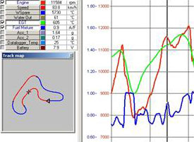 A typical data plot is included here to illustrate the levels of information
that, with a little effort, can be obtained. You will note that in this instance
the Air Fuel Ratio (the blue trace) is being recorded as a Lambda value. For
those of you that are eagle eyed you will also notice that at this point the
air/fuel mixture was dangerously lean, but this was a test session to
investigate this very area of the carbs performance and jetting envelope.
A typical data plot is included here to illustrate the levels of information
that, with a little effort, can be obtained. You will note that in this instance
the Air Fuel Ratio (the blue trace) is being recorded as a Lambda value. For
those of you that are eagle eyed you will also notice that at this point the
air/fuel mixture was dangerously lean, but this was a test session to
investigate this very area of the carbs performance and jetting envelope.
However the best datalogger and the only one that counts at the end of the day, is the stopwatch and with this simple tool coupled with some level of driver feedback, the optimum jetting can be arrived at by most competent drivers. It is important that you record the changes you make to the jetting and carb setup and at least, the changes to the air temperature at the time of the jetting or carb setup change.
 So for a typical British summers day of say 15C, for a Senior Max start with
a main jet of 165 and a K27 needle at clip 2 (165/P2), for Junior Max 162/P2 and
for a Mini Max 148/P2. Go out and gently bring the engine (50-60C) and tyres up
to temperature before putting in some quick laps.
So for a typical British summers day of say 15C, for a Senior Max start with
a main jet of 165 and a K27 needle at clip 2 (165/P2), for Junior Max 162/P2 and
for a Mini Max 148/P2. Go out and gently bring the engine (50-60C) and tyres up
to temperature before putting in some quick laps.
If the engine hesitates and misfires below half maximum revs then the main jet is too rich. If the engine misfires above 3/4 of maximum revs (with the correct gearing) then you are too lean.
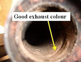
A quick check of the piston crown will also help. If it's black and wet you are too rich, black and dry spot on, any lighter colour then you may be too lean. I also like to check the exhaust header colour, which should be as illustrated here.
Come in, change to the next appropriate jet, record the air temperature and go out to test some more. You will quickly arrive, using this process, at the optimum main jet for the current conditions.
When you do, record your setup and the air temperature for future reference. Another method used to check the main jet is to slowly lift the carb choke lever as you are driving down the straight, if the engine slows you are too rich if it picks up you are too lean. Now, having found the correct main jet repeat this process for the needle clip position, again recording the settings and air temperature as above.
You will find, by using this simple process, each time you visit the track you will start to build your own database of air temperature versus jetting from which you will be able to better predict the jetting required on a particular day. However I have to say good jetting software will make your life a lot easer, allowing valuable time to concentrate on setting up your chassis and tyre combination.
A final word: All engines need fuel to make power and jetting leaner, may not always be the way to go. It may sometimes be your selection of spark plug that is wrong and not your jetting selection. This is often true in the colder months when you may well benefit from using a hotter plug type, such as the NGK BR8 EG, however be careful with this one as hot plugs and lean jetting quickly lead to engine damage.
 Be fast and stay safe!
John Savage is the Author of Jet-Tech - The Ultimate Jetting & Kart Set-up Software, which is designed for the entire Dellorto range of carburettors and is available on CDROM from www.rotaxjetting.com.
All email enquires should be addressed to Colin at info@rotaxjetting.com
.© Jet-Tech Motorsport Limited 2008 All rights reserved.
| News | Karts & Karting |
Notice Board |
Market Place |
Companies Directory |
Tracks Directory |
Events Calendar |
Race Results |
Photo Gallery |
Links |
Copyright © 1996-2018 UK Karting Comments, Suggestions etc. mail@karting.co.uk |